Submitted by: Greg Hunolt
May, 2010
This article is another in the continuing WARCI News series about Wisconsin radio companies.
The Wisconsin Historical Society (WHS) website reports that Martin Winther incorporated the Winther Motor and Truck Company in December 1916 in Kenosha, Wisconsin, with his younger brother Anthony Winther working for him. The company shipped 500 Winther automobiles to Australia in 1917, but with the onset of World War I the company began making trucks and in 1918 received a contract from the U.S. Army to assemble four-wheel drive trucks. Following the war, Winther resumed production of Winther automobiles. In 1923 Martin Winther re-incorporated the company in Kenosha as the Winther Motor Company, and began using the trade name “Winther-Kenosha” for most of its products. The company was reorganized again in 1926 as the Kenosha Fire Engine and Truck Company, and in 1927 the company was sold. The Winther brothers went on with their careers in business. The WHS notes that although Martin and Anthony only attended school through the eighth grade, the two of them (separately or together) were granted patents for almost 300 car- and truck-related mechanical devices, including the first successful air conditioning system for Pullman railroad cars. See the WHS website for the full story of the Winther brothers’ career.
 Fig 1 – W-K Electric ad, Radio Industry, June 1925
Meanwhile, the W-K Electric Company of Kenosha advertised the “new Five Tube Oriole Receiver” in Radio Industry magazine in June, 1925, November 1925, and March 1926. See figure 1 for the June, 1925 ad. W-K advertised the model 71 “The Warwick”, the model 75 “The Canterbury”, and “The Mayfair” receivers in Radio Retailing in October 1926 and Radio Broadcast and Popular Radio in November 1926. See figure 2 for the November, 1926, Radio Broadcast ad.
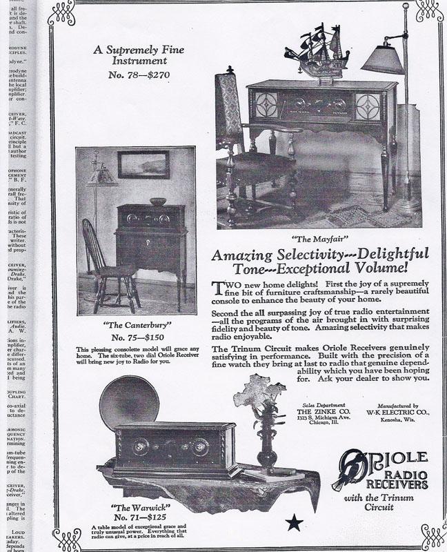 Fig 2 – Radio Broadcast, November 1926
Was there a connection between the Winther brothers of the Winther Motor Company of Kenosha and W-K Electric of Kenosha? The fact that the Winther had adopted the Winther-Kenosha trade name – which one can imagine being abbreviated “W-K” – suggests a connection. But the clincher is patent number 1,700,393 for “Radio Frequency Amplification Circuits” issued to Anthony Winther of Kenosha, listed as the inventor. The patent application was filed on May 13, 1925, and the patent was granted in on January 29, 1929. By that time the Winthers had sold the Winther company, and the patent was assigned to the All-American Mohawk Company of Chicago, Illinois, suggesting that Anthony Winther had sold the patent to Mohawk by that date.
See figure 3 for the title and diagram from the Winther patent.
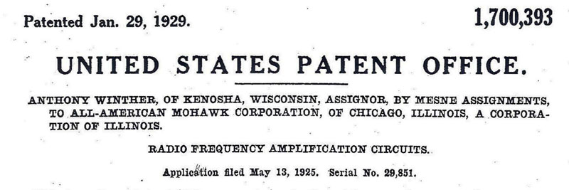
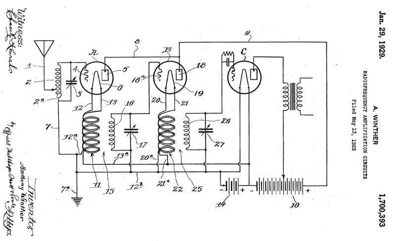
Fig 3 – Winther Patent Title and Diagram
The Winther patent was for a vacuum tube radio frequency amplifier stage circuit that is now known as the “cathode follower”. In what was the customary configuration, the amplifier stage would use plate loading, meaning that the ouput of the stage was produced across a load (e.g. either a transformer or resistor depending on the interstage coupling being used) in the tube’s plate circuit, i.e. between the plate and ground. In Winther’s design, the output load is between the tube’s cathode (which was the filament in tubes such as the 01A) and ground, and Winther’s schematic shows an RF amplifier stage with an RF transformer in between the cathode and ground for inductive coupling to the next stage. The benefit of this approach, according to Winther, was improved efficiency and selectivity. (The term “cathode follower” derives from the fact that the output signal taken across a cathode load is in phase with, and hence “follows”, the input signal, while the output signal taken across a plate load would be 180 degrees out of phase with the input signal.)
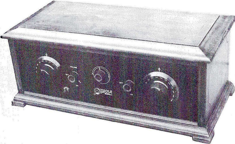 Fig 4 – Oriole Model 7B
Antique Radio Classified, December 1989, carried a photograph of an Oriole model 7B receiver submitted by Robert Gordon of Muskego, Wisconsin, shown here as figure 4. In his description of the set, Mr. Gordon noted the use of the cathode follower configuration in the two RF amplifier stages. His 7B schematic is reproduced here as figure 5. Note the transformer coupling between RF stages in the filament (i.e. cathode) circuit consistent with the Winther patent diagram (figure 3 above).
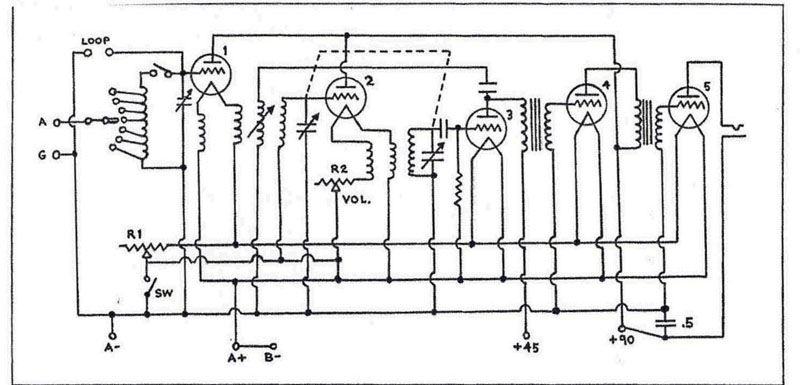 Fig 5 – Oriole 7B Schematic
The 1925 ads for the Five Tube Oriole Receiver (see figure 1) mention proclaim that “Built on an entirely new principle, with a circuit never used before, the Oriole has no superior for selectivity, volume, and pure tone”. The “Five Tube Oriole Receiver” in the ads appears to be the Model 7B. The 1926 ads for the models 70, 75 and 78 tout the sets’ “amazing selectivity, delightful tone, and exceptional volume” pointing to their use of the “Trinum Circuit”. In December, 1926, Radio News magazine awarded the “Oriole Trinum” radio receiver (which appears to be the model 71 “Warwick”) its Radio New Laboratories Certificate of Merit.
Figures 6 and 7 show the Oriole Model 8 receiver, a four tube set from 1925.
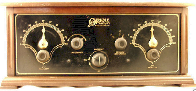 Fig 6 – Oriole Model 8
 Fig 7 – Oriole Model 8
Figures 8 shows John Stroebel’s model 200 Oriole receiver. This set has an inside nameplate that says “Oriole Receiver Model 200, Serial 2164. Warning: The Trinum Circuit used on this receiver is patented. Any infringement will be prosecuted. W-K Electric Co., Kenosha, WI”. No patent number is cited, suggesting that when the radio was produced the patent application had been filed but not yet granted, which is consistent with the time frame for the Winther patent.
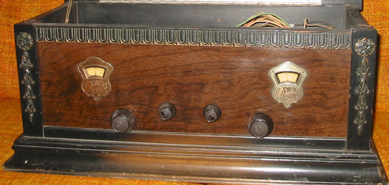 Fig 8 – John Stroebel’s 1927 Oriole Trinium Model 200
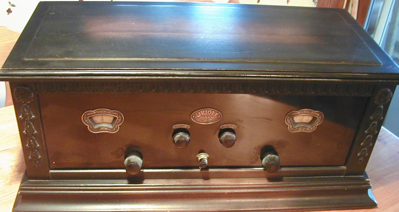 Fig 9 – 1927 Oriole “Junior” Trinium Model 90
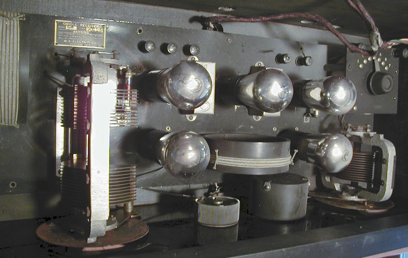 Fig 10 – Oriole “Junior” Model 90 Chassis
Note that neither the Winther patent nor the 1925 ads mention the name “Trinum” for the circuit, but it seems safe to conclude that the “Trinum Circuit” referred to the cathode follower configuration described in the Winther patent and that W-K Electric was operated in Kenosha by Anthony and possibly Martin Winther in parallel with or as part of their Winther Motor Company.
The table below (taken from the 2010 edition of the Battery Set Compendium to be released in May or June 2010) lists receivers manufactured by W-K Electric according to the best information I have found so far. I believe the first two receivers, Models 5 and 6, were manufactured in 1924 – perhaps a stretch given that the earliest reference to them was in the portion of the 1925 Radio News Radio Set Directory published in the October 1925 issue. The last receivers are listed as 1927 models. Dale Boyce mentioned a booklet describing 1927-1928 models, but it seems most likely that W-K Electric ceased production at about the same time as the sale of Winthers’ Kenosha Fire Engine and Truck Company in 1927.
Table: Radios Manufactured by W-K Electric (Battery Set Compendium 2010 edition)
| Year | Model | Cabinet | Tubes |
|---|---|---|---|
| 1924 | W-K Oriole Model 5 Receiver | Table-Low | 4 |
| W-K Oriole Model 6 Receiver | Table-High | 4 | |
| 1925 | W-K Oriole Model 60 | Table-Low | 5 |
| W-K Oriole Model 7 Receiver | Table-High | 5 | |
| W-K Oriole Model 7-B Receiver | Table-Low | 5 | |
| W-K Oriole Model 8 Receiver | Table-Low | 4 | |
| 1926 | W-K Oriole Model 7-D Receiver | Table-Low | 5 |
| W-K Oriole Model 70 Receiver | Table-Low | 6 | |
| W-K Oriole Model 71 "Warwick" Receiver | Table-Low | 6 | |
| W-K Oriole Model 71S Receiver Chassis | Table-Low | 6 | |
| W-K Oriole Model 72 Receiver | Table-Low | 6 | |
| W-K Oriole Model 75 "Canterbury" Console Receiver | Console | 6 | |
| W-K Oriole Model 78 "Mayfair" Console | Console-Desk | 6 | |
| 1927 | W-K Oriole Model 100 Trinum Receiver | Table-Low | 8 |
| W-K Oriole Model 200 Trinum Receiver | Table-Low | 5 | |
| W-K Oriole Model 90 "Junior" Receiver | Table-Low | 5 |
Figures 9 and 10 show an Oriole Model 90 “Junior” five tube receiver. Note the similarity of the chassis to the model 7B chassis shown in figure 11. A new design element on the front panel is the use of the small escutcheons around the tuning dials. Compare with the a bit more elaborate escutcheon work on the model 200, figure 8 above.
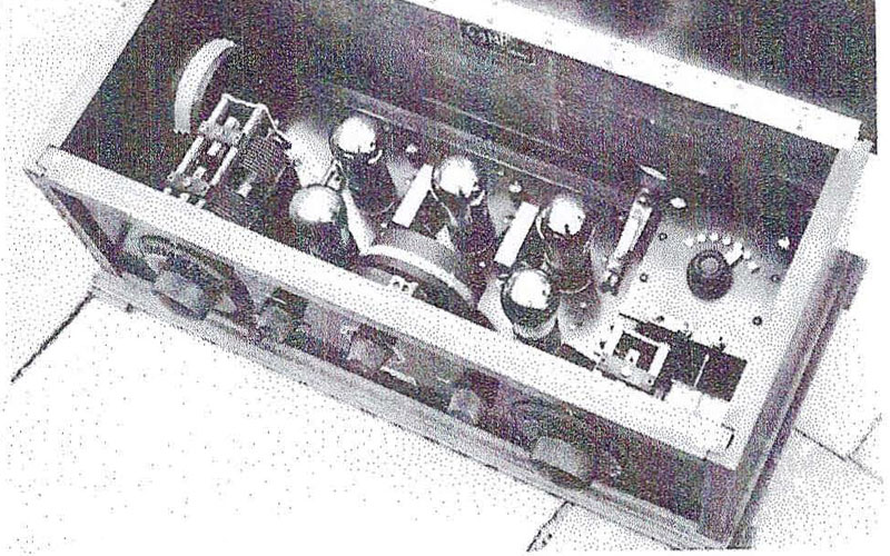 Fig 11 – Oriole 7B Chassis
Any information adding to or correcting the discussion of W-K Electric and their radios would be most welcome!
Acknowledgments – with the author’s thanks:
Wisconsin Historical Society website http://www.wisconsinhistory.org/whi/feature/winther/
John Stroebel provided photos of his Oriole 200, a copy of the patent, and the link to the WHS website. John noted that while he is currently living in Minneapolis his roots are in the Milwaukee area. He believes that his grandfather worked for W-K in the mid to late 20’s but lost his job in 1929 during the Great Depression.
“The Oriole Model 7B”, Robert Gordon, Antique Radio Classified, December 1989, p.8, copyright 1989 by John V. Terrey. Information from the article, including the photo of the Oriole 7B and its schematic are reprinted with permission from Antique Radio Classified (antiqueradio.com), P.O. Box 2, Carlisle, MA 01741 USA.
Dale Boyce provided information about the W-K Electric Oriole sets in his collection.